Borosilicate 3.3 Shell and Tube Heat Exchangers
Goel Glass supplies high-performance Borosilicate Glass 3.3 Shell and Tube Heat Exchangers designed specifically for aggressive thermal duties across the chemical synthesis, pharmaceutical manufacturing, botanical extraction, and acid recovery sectors. Engineered to deliver vast heat exchange surface areas (from 0.3 m² to over 25 m²) within a remarkably compact footprint, these units set the industrial benchmark for condensation, vapor chilling, reboiling, and liquid-liquid thermal recovery.
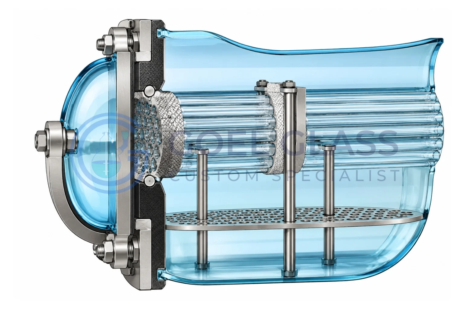
Every exchanger integrates precision-drawn, jointless Borosilicate 3.3 glass tube bundles individually retained in solid virgin PTFE tube sheets. This construction establishes an exceptionally inert wetted contact boundary immune to halogen attack, mineral acid degradation, and organic solvent corrosion (with the sole exception of HF and hot concentrated alkalis). The mirror-smooth, non-porous glass surfaces completely resist product fouling and scale formation while providing uninterrupted visual monitoring of internal phase changes.
- Uncompromised Corrosion Immunity: Delivers complete chemical resistance against hot boiling acids (HCl, H₂SO₄, HNO₃), serving as a cost-effective, zero-contamination alternative to Tantalum, Hastelloy, Titanium, and resin-impregnated graphite blocks.
- Superior Overall Heat Transfer Rates: Eliminates fouling factors entirely; segmented baffle architecture induces cross-flow turbulence to achieve global U-values up to three times greater than traditional coil exchangers.
- Low Hydraulic Resistance: Straight-through parallel tube circuits avoid vapor choking and keep pressure drops negligible compared to narrow coil conduits.
- Independent Tube Serviceability: Each glass tube is secured with an individual PTFE compression socket, enabling on-site inspection, cleaning, or single-tube replacement without discarding the bundle.
- Thermal Stress Decoupling: Floating tube-sheet geometry accommodates differential thermal expansion between the glass bundle and outer housing, ensuring long-term mechanical reliability under cyclic thermal loads.
- Versatile Process Orientation: Configurable for vertical reflux overhead condensation or horizontal liquid-liquid process mounting.
Key Technical Advantages:
- Enhanced Overall Heat Transfer Coefficient: By maximizing turbulent cross-flow across precision-pitched glass tube arrays, shell and tube exchangers deliver overall U-values roughly triple those of static helical coil arrangements.
- Substantially Lower Process Pressure Drop: Vapor and fluid streams encounter minimal hydraulic resistance through straight parallel tubes, eliminating the 2–3 bar pressure penalties common in restrictive coil coils and protecting delicate vacuum distillation levels.
- Unrestricted Heat Transfer Scalability: While coil-in-shell units are geometrically constrained to smaller capacities, modular shell and tube arrays easily expand from pilot-scale 0.3 m² up to 25+ m² industrial installations.
Thermodynamic Comparison: Shell & Tube vs. Conventional Coil Condensers
Mechanical Design & Sealing Integrity
The tube bundle utilizes high-grade, seamless Borosilicate 3.3 tubing anchored into solid PTFE tube plates. Each individual tube is sealed using precision virgin PTFE ferrule sockets and elastomeric O-ring energizers, creating a completely hermetic seal that simultaneously permits free axial expansion. Strategic PTFE baffles situated along the shell channel direct fluid across the bundle perpendicularly, disrupting stagnant boundary layers and elevating thermal convective coefficients throughout the entire shell volume.
- Precision-drawn borosilicate 3.3 seamless tubing ensures uniform wall thickness and certified pressure ratings.
- Wetted contact parts are restricted entirely to Borosilicate Glass 3.3 and virgin PTFE for 100% trace metal-free purity.
Available Structural Configurations:
Goel Glass provides three standardized material configurations engineered to match process media aggressiveness:
| MATERIAL OF CONSTRUCTION OF SHELL & TUBE HEAT EXCHANGER | ||||
|---|---|---|---|---|
| Model | Shell | Tube | Header | Duty |
| RGG | Glass | Glass | Glass | All-Glass Sanitary/Corrosive Duty: Engineered for processes where both process fluids and service utilities are aggressive or require zero-metal purity (e.g. acid condensing with chilled corrosive brine). |
| RGM | Glass | Glass | Steel/FRP | Corrosive Shell / Non-Corrosive Tube: Handles aggressive process vapors or boiling media within the glass shell, utilizing plant steam or non-corrosive cooling water inside the tube pass. |
| RMG | Steel/FRP | Glass | Glass | Corrosive Tube / Non-Corrosive Shell: Routes highly corrosive chemical media through the glass tubes, utilizing industrial plant utilities within an economical, rugged metallic or FRP shell. |
Dimensional Specifications :
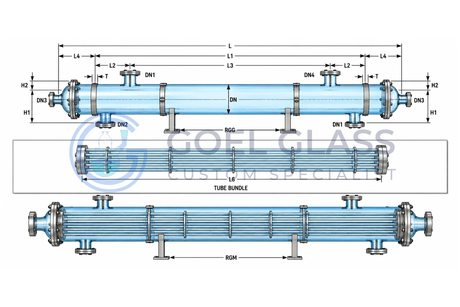
| Cat.Ref. RGG/RMG |
6/3 | 6/4 | 6/5 | 6/6 | 9/6 | 9/8 | 9/10 | 9/12 | 12/12 | 12/16 | 12/21 | 12/25 | 16/21 | 16/25 |
|---|---|---|---|---|---|---|---|---|---|---|---|---|---|---|
| Area (m2) | 3 | 4 | 5 | 6 | 6 | 8 | 10 | 12 | 12 | 16 | 21 | 25 | 21 | 25 |
| DN | 150 | 225 | 300 | 400 | ||||||||||
| DN1 | 80 | 100 | 150 | 225 | ||||||||||
| DN2 | 50 | 80 | 80 | 100 | ||||||||||
| DN3 | 25 | 40 | 40 | 50 | ||||||||||
| DN4 | 50 | 50 | 50 | 80 | ||||||||||
| H1 | 175 | 250 | 300 | 450 | ||||||||||
| H2 | 150 | 200 | 250 | 300 | ||||||||||
| L | 2500 | 3100 | 3700 | 4300 | 2620 | 3220 | 3820 | 4520 | 2550 | 3150 | 3950 | 4550 | 3100 | 3500 |
| L1 | 1900 | 2500 | 3100 | 3700 | 1900 | 2500 | 3100 | 3800 | 1800 | 2400 | 3200 | 3800 | 2000 | 2400 |
| L2 | 150 | 150 | 150 | 150 | 225 | 225 | 225 | 225 | 225 | 225 | 225 | 225 | 400 | 400 |
| L3 | 1600 | 2200 | 2800 | 3400 | 1450 | 2050 | 2650 | 3350 | 1350 | 1950 | 2750 | 3350 | 1200 | 1600 |
| L4 | 250 | 250 | 250 | 250 | 300 | 300 | 300 | 300 | 300 | 300 | 300 | 300 | 550 | 550 |
| L5 | 125 | 125 | 125 | 125 | 175 | 175 | 175 | 175 | 175 | 175 | 175 | 175 | 225 | 225 |
| L6 | 1980 | 2580 | 3180 | 3780 | 2000 | 2600 | 3200 | 3900 | 1930 | 2530 | 3330 | 3930 | 2185 | 2585 |
| T | 50 | 60 | 75 | 100 | ||||||||||
| No. of Tubes | 37 | 73 | 151 | 241 | ||||||||||
| No. of Baffles | 11 | 15 | 19 | 23 | 7 | 9 | 13 | 17 | 5 | 7 | 9 | 11 | 5 | 7 |
Operational Limits & Boundary Conditions:
Permissible Thermal Spectrum: Continuous operating temperature rating from -40°C to +150°C across both shell and tube pathways.
Thermal Shock Tolerance: Accommodates acute temperature differentials (ΔT) up to 120°C between process and utility media without thermal stress fracture.
Vacuum & Pressure Integrity: Every standard model is rated for full vacuum duty down to -1.0 bar g (ideal for high-vacuum fractional distillation). Certified positive operating pressures vary by nominal shell diameter as detailed in the technical schedule below:
| MAXIMUM PERMISSIBLE PRESSURE RANGE, KG/CM2(G) | ||||
|---|---|---|---|---|
| Model | Side | 150DN | 225DN | 300DN |
| RGG | Shell-Tube Tube-Glass Dome-Glass |
2.0 2.0 |
1.0 1.0 |
1.0 1.0 |
| RGM | Shell-Tube Tube-Glass Dome-Glass |
2.0 3.5 |
1.0 3.5 |
1.0 3.5 |
| RMG | Shell-Tube Tube-Glass Dome-Glass |
3.5 2.0 |
3.5 1.0 |
3.5 1.0 |
The above ranges of applications are admissible limiting values. For each specific process case, Goel Glass engineering provides calibrated operating data based on the dynamic interplay of operating pressure, process temperature, vessel geometry, and operational mode.
Thermal Performance & Sizing Methodology:
The primary operational benefit of the borosilicate shell and tube design is exceptional thermodynamic efficiency driven by controlled flow velocity. Our engineering specialists analyze your operating parameters—including mass flow rates, physical property data, log mean temperature difference (LMTD), and permissible pressure drop—to determine the optimal shell diameter, tube count, and baffle spacing. The representative heat transfer coefficients tabulated below serve as initial sizing benchmarks across common condensation and liquid-cooling services:
| U-VALUES | |||
|---|---|---|---|
| Media | Use | kcal/m2hrk | W/m2k300 |
| Steam water | condensation | 350-550 | 410-640 |
| Water – water | cooling | 250-350 | 290-410 |
| Water – air | cooling | 30-60 | 35-70 |
Frequently Asked Questions
Borosilicate Glass 3.3 paired with virgin PTFE offers near-universal corrosion resistance across nearly all mineral acids, halogens, and organic solvents at a fraction of the capital cost of Tantalum, Hastelloy, or Titanium. Unlike impregnated graphite blocks, glass cannot leach resins, absorb flavors, or cross-contaminate high-purity pharmaceutical batches. Furthermore, transparent glass enables 360-degree real-time visual inspection of condensation dynamics, fouling, and flooding.
Shell and tube units deliver overall heat transfer coefficients up to three times higher than helical coil condensers due to engineered cross-flow turbulence induced by internal PTFE baffles. Crucially, they exhibit virtually negligible process pressure drop through straight, parallel tubes—avoiding the 2 to 3 bar pressure penalties typical of coil sides. Shell and tube exchangers also scale to massive surface areas (up to 25+ m²) in a compact vertical or horizontal envelope.
Yes. Unlike welded metallic bundles or glued graphite blocks, Goel Glass units feature independent PTFE compression sockets for each individual tube. If a tube is compromised due to mechanical impact, plant operators can isolate and replace only the affected tube without replacing the entire bundle, drastically cutting maintenance expenses and minimizing plant downtime.
Our engineering utilizes a floating tube-sheet configuration supported by precision-machined PTFE ferrule packing. Because borosilicate 3.3 has an extremely low coefficient of thermal expansion (3.3 × 10⁻⁶ K⁻¹), each tube can freely expand and contract axially within its PTFE seating without exerting mechanical strain on the glass shell or headers.
To calculate your required heat transfer area and hydraulic parameters, please share your process stream data (flow rates, inlet and target outlet temperatures, operating pressure, heat duty or latent heat of vaporization), media physical properties (specific heat, viscosity, thermal conductivity), and available utility conditions (cooling water temperature or steam pressure). Contact our Toronto engineering team at canada@goelglass.com for a customized thermal specification.